The clutch-brake unit is the heart of a mechanical press’s control system. It determines when the crankshaft turns, how quickly the ram stops, and — critically — whether the press can be stopped safely at any point in the stroke. Getting it wrong means safety failures, unplanned downtime, and expensive repairs.
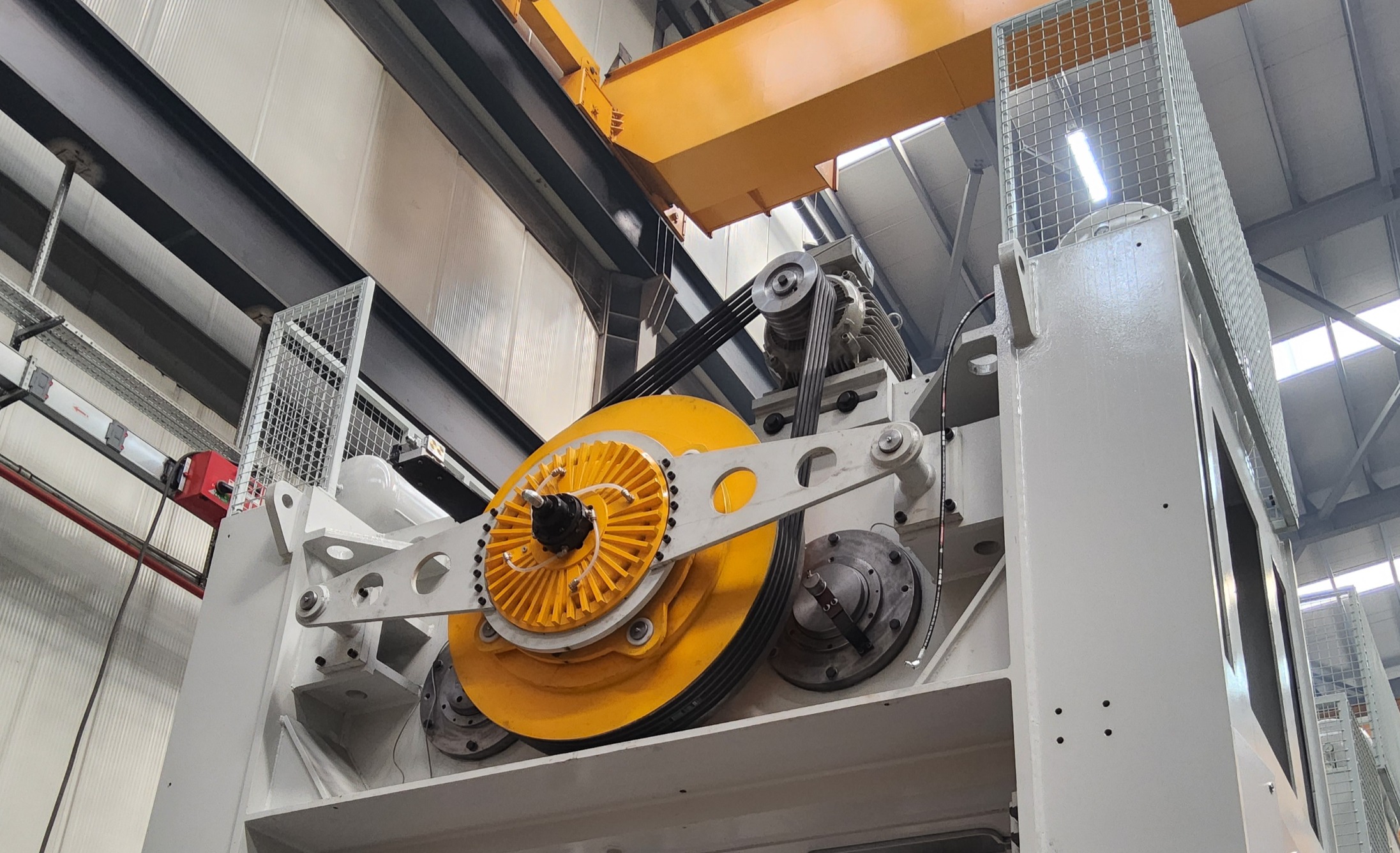
 Clutch-Brake Unit on a Mechanical Press Flywheel
The Three Major Types
1. Mechanical (Jaw/Dog) Clutch-Brake
The oldest design — a rotating jaw on the flywheel engages a matching jaw on the crankshaft.
Pros:
- Simple, low-cost construction
- Very high torque capacity relative to size
- Minimal slip during engagement
Cons:
- Can only engage at one specific crankshaft position (top of stroke)
- No mid-stroke stopping capability → fails ISO 13849 PLe safety requirements
- High shock loads on engagement → accelerated wear on drivetrain
Use case: Old, non-CE-marked presses running simple blanking at fixed speeds. Not suitable for new machinery or any application requiring mid-stroke stop.
2. Pneumatic Friction Clutch-Brake
The dominant technology for modern mechanical presses. A pneumatic piston clamps friction discs between clutch and brake elements.
Pros:
- Can engage and disengage at any crankshaft position
- Smooth torque build-up → low shock loads
- Fast response time (typically 20–80 ms)
- Can achieve Category 3 / PLd or PLe safety with dual-valve monitoring
- Relatively low maintenance
Cons:
- Requires clean, dry compressed air supply
- Friction disc wear → periodic replacement required
- Performance degrades at high cycle rates (heat build-up in discs)
Use case: The default choice for nearly all modern general-purpose mechanical presses from 50 to 4000+ tons. Works with automated feeding, progressive dies, and robotic integration.
Key selection parameters:
- Torque capacity — must exceed peak crankshaft torque at rated tonnage height
- Stopping angle — the crankshaft angle swept from signal to full stop; governs safety distance calculations per ISO 13855
- Thermal capacity — cycles per minute × energy per cycle must stay within rated limits
3. Hydraulic Clutch-Brake
Uses hydraulic pressure instead of pneumatic — less common, but used in very large or high-precision presses.
Pros:
- Higher clamping force at lower pressure → compact for very high torques
- More consistent torque in high-temperature environments
- Very precise stopping angle control
Cons:
- Requires a hydraulic power unit → added complexity and cost
- Oil contamination risk on friction surfaces
- Slower response time than pneumatic (typically 80–200 ms)
- Higher maintenance burden
Use case: Heavy-duty forging presses above 2000 tons, or precision presses where stopping repeatability is critical.
Selection Criteria Summary
| Criterion | Mechanical (Jaw) | Pneumatic Friction | Hydraulic |
|---|---|---|---|
| Mid-stroke stop | ✗ | ✓ | ✓ |
| ISO 13849 PLe | ✗ | ✓ (with dual valve) | ✓ |
| Stopping time | Fixed (one point) | 20–80 ms | 80–200 ms |
| Maintenance | Low | Medium | High |
| Cost | Low | Medium | High |
| High cycle rate | Poor | Good | Moderate |
| Very high torque | Good | Good | Best |
The Most Overlooked Parameter: Stopping Angle
Engineers focus on torque capacity but often neglect stopping angle — the crankshaft degrees from the stop signal to full standstill. This directly determines the minimum safety distance between the operator’s hands and the tooling, per ISO 13855:
Ds = K × (Ts + Tc + Tr + Tbm)Where Ts is the press stopping time. A slower-stopping clutch-brake forces a larger safety distance, which may make light curtain guarding impractical for the tool size.
Always request the stopping performance curve (stopping angle vs. crankshaft speed) from the clutch-brake manufacturer before finalizing your safety system design.
Emrah Demirezen — Metal Forming Specialist, Press Design Engineer
info@demirezenengineering.com